
TL;DR
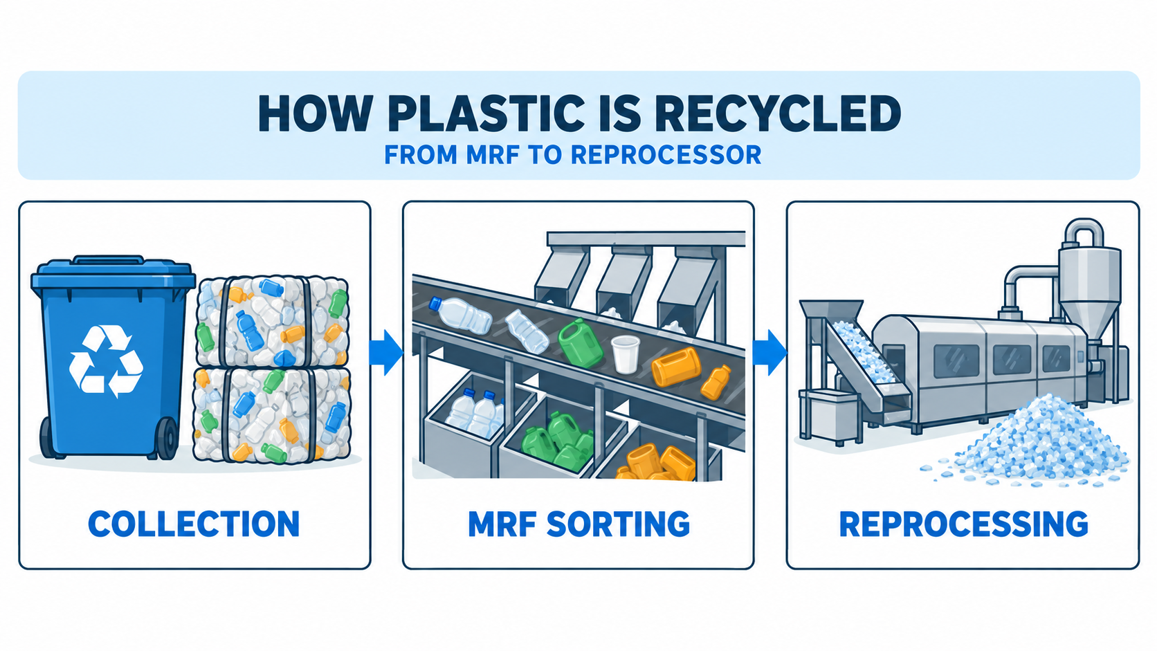
Plastic recycling is a chain, not one machine step. Collection and MRF sorting prepare material; a mechanical recycler may sort, reduce size, wash, separate, dry and extrude it. Operations and order can vary or repeat with the feedstock and required output.
Abstract
This guide separates public collection and MRF sorting from industrial recycler processing, then follows mechanical-recycling stages and explains why sequence depends on feedstock and intended output.
Key Takeaways
- Collection and MRF sorting are upstream handoffs, not the recycler’s full processing line.
- Mechanical recycling changes material through sorting, size reduction, cleaning, separation and, where applicable, extrusion.
- A process diagram is a representative route, not a universal recipe for every plastic stream.
- Size reduction prepares plastic for downstream cleaning and separation; it is not the finished recycled output.
- Read each stage by its input, purpose and output rather than by a fixed step count.
Where does plastic recycling start, and where does the recycler take over?
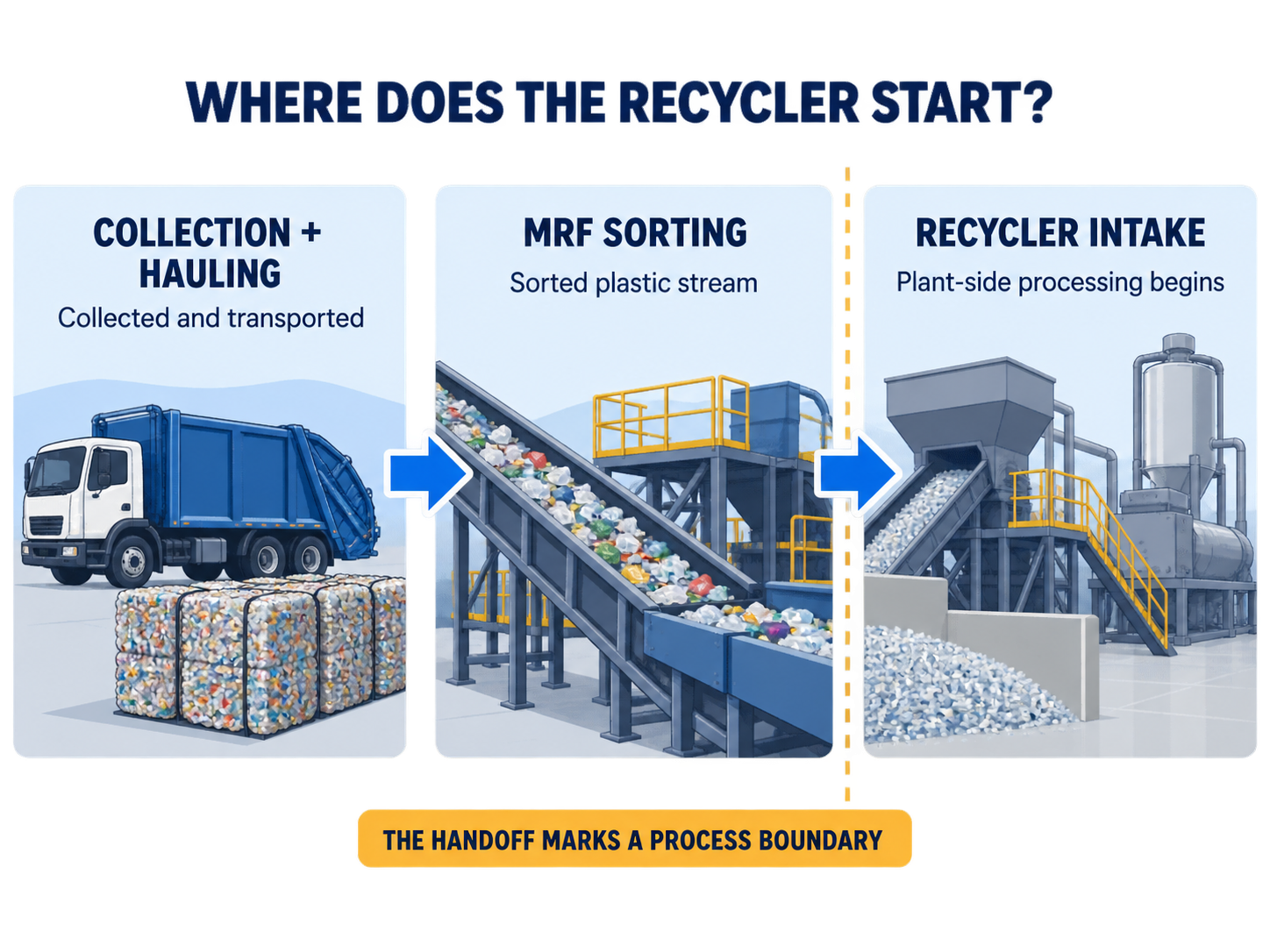
Plastic recycling is a chain of handoffs, not a single machine operation. Collection and sorting at a material recovery facility (MRF) prepare material for a plastics recycler; the recycler then carries out industrial processing, and recovered material can move on to manufacturers.
Collection and material recovery
Collection and hauling bring discarded plastics into the recovery system. At an MRF, incoming materials are sorted into streams and prepared for shipment, often as bales. That work is upstream of the plastic recycler’s own line. A recycling diagram that begins with household collection therefore describes a broader system than one that begins at the recycler’s receiving area.
The handoff from MRF to recycler
After a recycler receives a stream, its plant may inspect and sort incoming material again before size reduction and cleaning. The exact boundary varies: one operator may receive a more-prepared stream, while another may carry out additional sorting or process control on site. This is one reason published descriptions do not all show the same number of stages.
Keep the distinction in mind as you read the process below. The MRF prepares and separates incoming material; the recycler’s line changes that material into a cleaner, more usable intermediate or recycled output. These are connected stages, but they are not interchangeable labels for the same machine line.
The Association of Plastic Recyclers (APR) illustrates the public-side route with 3 steps: recycling bin, haulers, and a material recovery facility (MRF), then identifies recyclers as Step 4. This system-level map describes one recovery chain; it is not a universal municipal sequence or a prescribed number of operations inside every recycler’s plant.
What happens to plastic inside a mechanical recycling plant?
A mechanical recycler receives a plastic stream and uses a sequence of preparation, size reduction and cleaning operations to produce a material that can move to the next process. A representative route may include opening and checking bales, further sorting, grinding or shredding, washing, separation and drying. Some lines also extrude or compound the material on site. The sequence is not a universal recipe.
A representative plant-side route
The table is a map of operations described by recycling-industry and technical sources. It is meant to show what changes at each stage, not to specify the equipment every plant must install. A facility may receive material at a different starting point, combine operations, or send an intermediate output elsewhere.
The Association of Plastic Recyclers, Plastics Europe, and TWI describe related operations from different process boundaries. Read together, their examples support a representative process map, not one required sequence for every facility.
| Stage | Purpose | Intermediate output | What may vary |
|---|---|---|---|
| Bale opening and receiving check | Loosen incoming material and assess the feed | Opened material ready for handling | The recycler may receive material in a different form |
| Sorting and process control | Separate material outside the target stream | A more consistent plastic fraction | Sorting can happen upstream, at the recycler, or at more than one point |
| Size reduction | Make plastic pieces smaller for subsequent operations | Flake or smaller fragments | Equipment and terminology differ by line |
| Washing | Remove material that can be released through the chosen cleaning process | Washed plastic pieces | Cleaning stages may be combined or repeated |
| Separation and drying | Separate fractions where used and prepare material for the next operation | A separated or dried intermediate | The method and location depend on the line |
| Extrusion or compounding, when included | Convert prepared material into a further processed form | Pellets or compounded material | Some recyclers provide an earlier intermediate instead |
Purpose and output at each stage
The first operations handle the incoming form. Bale opening makes the material accessible to the line, while inspection and sorting help direct an appropriate stream forward. Some material recovery happens before the recycler receives a bale, but additional checks may still take place at the plant.
APR describes one recycler-side example that separates incoming material into 3 streams: intended plastic, missorted plastic containers, and waste. This shows why a recycler may sort material again after receiving an MRF-prepared bale. The example illustrates one possible plant-side check; it does not prescribe a fixed stream count or sorting layout for every facility.
Size reduction changes the physical form of the plastic. APR describes grinding material into flake before washing and float-sink separation in its account of a recycler’s process. Other process overviews use different labels or place operations in a different order, so treat the table as a guide to function rather than a mandatory sequence.
Washing and separation address different parts of the job. Washing cleans the material; a density-based separation stage, where the line uses one, separates material fractions. Drying prepares the processed pieces for a later operation. These steps can be adjacent or arranged differently, and one source’s diagram may count a combined operation as one stage while another separates it into several.
The endpoint also depends on what the recycler produces. A line may prepare clean flake for a downstream user, or it may continue through extrusion or compounding to a more processed output such as pellets. Do not assume that every recycling facility performs every operation on site. The most reliable way to read a plant diagram is to note its stated input and output, as well as which organization performs each handoff.
Why can recycling stages change order or repeat?
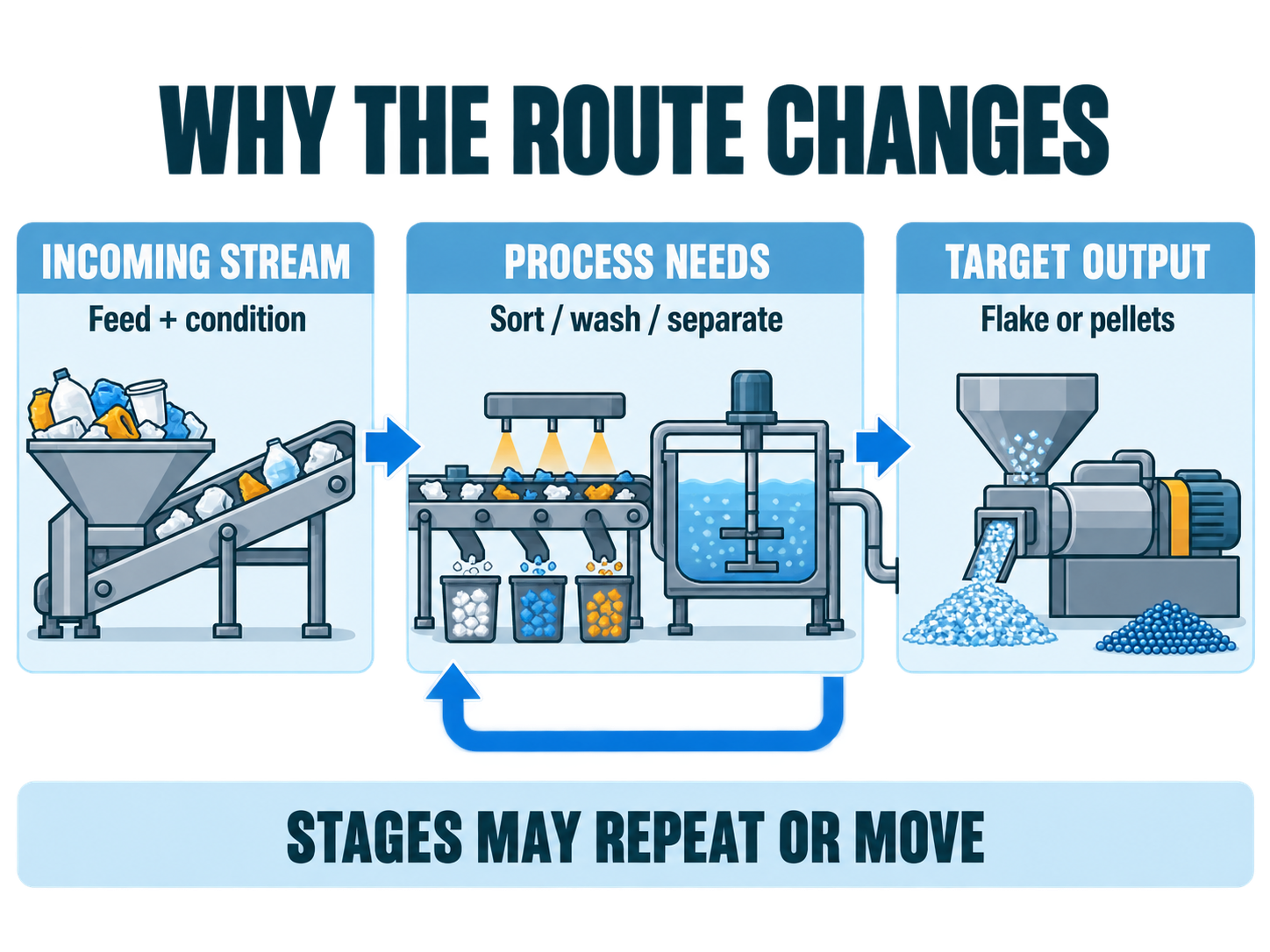
Plastic recycling diagrams can show different sequences because they may start at different points, describe different plant boundaries, or reflect different material streams. Even within mechanical recycling, sorting, washing, drying and separation do not have to appear once each in one fixed order. A technical overview notes that stages may change order or repeat according to the composition of the waste.
Feedstock condition changes the work needed
Start with the incoming stream. Its composition and condition affect what the line needs to separate, clean or prepare. If a diagram shows an additional sorting or washing operation, that does not automatically mean the other diagram is wrong. The two may be describing different feedstock, different process boundaries or different levels of detail.
A common misconception is that one step count defines the whole recycling process. The sources show why that is unreliable: a diagram may include collection and MRF sorting, or begin at the recycler, and may stop at an intermediate material or a later output.
Some process descriptions show sorting at more than one point. For example, one overview distinguishes initial sorting from a later sorting or control step. That is evidence of a possible staged arrangement, not proof that every recycler repeats the same operation.
The intended output sets the process endpoint
A recycler’s target output affects how far the on-site line continues. One route may stop at a prepared flake or another intermediate material. Another may include additional drying, extrusion or compounding. When two diagrams appear to disagree, check what each calls its finished output before comparing the number of boxes.
Important: A process diagram is a description of a route, not a universal plant specification. Stages can move, combine or repeat as the incoming stream and intended output change.
The useful question is not “Which diagram has the correct number of steps?” It is “What material enters this stage, what operation is performed, and what output leaves?” That framing explains why a concise overview and a detailed facility description may both be accurate without matching box for box.
Before comparing two diagrams, note where each one starts and stops. One may include the MRF handoff while another begins at the recycler’s receiving area. Also check whether a source combines washing and drying under one label, or describes them separately. As a practical reading rule, a stage missing from a short overview may simply sit outside that source’s chosen boundary; it does not prove that the operation never occurs elsewhere. Only facility-specific documentation can confirm the exact installed route.
Where do shredding and grinding fit in the plastic recycling process?
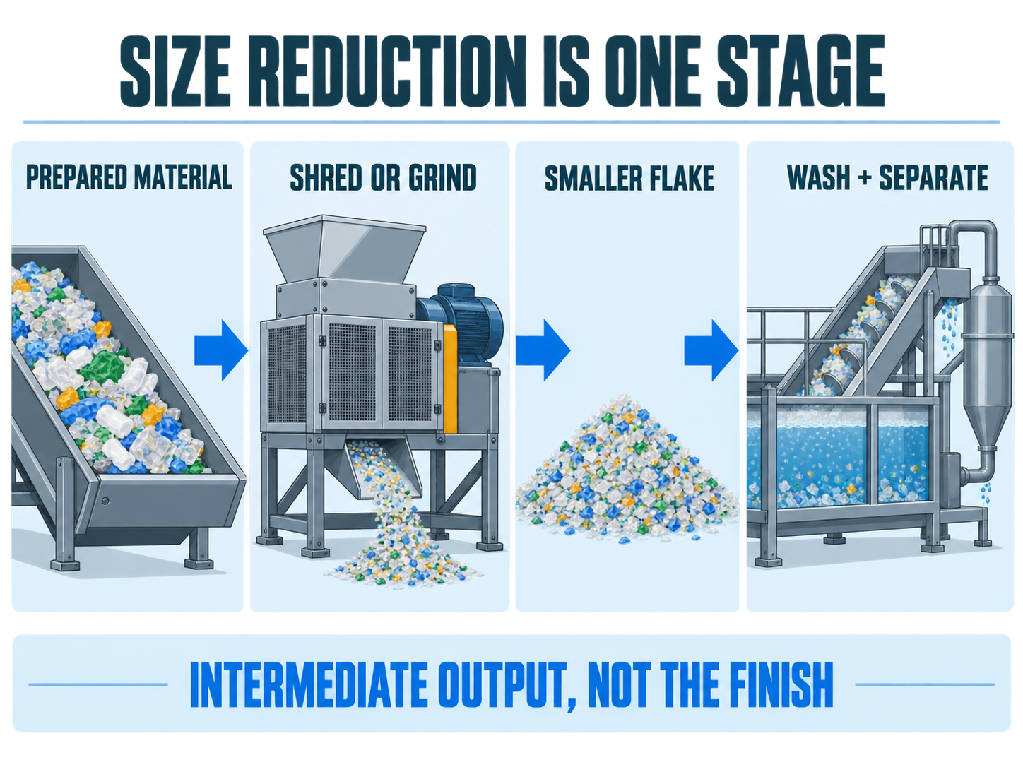
Shredding and grinding belong to the size-reduction part of the route. They change prepared plastic into smaller pieces so it can move through later processing; they do not, by themselves, wash or separate the material or turn it into a finished recycled product.
Size reduction changes the material form
A recycler may carry out size reduction after receiving and sorting material. The resulting pieces may be described as flake or fragments, depending on the process and the source’s terminology. One published recycler-side sequence places grinding before washing and float-sink separation. That is an example of where size reduction can fit, not a fixed layout for every plant.
The important point is the change in material form, not a specific machine specification. A process illustration cannot tell you the finished particle size, rotor arrangement or line capacity unless those details are separately documented. This guide therefore keeps the explanation at the stage level: material is reduced, then the following operations handle cleaning and separation as required by that route.
Important: Smaller pieces are still an intermediate material. Cleaning, separation and any further processing required for the intended output remain separate parts of the route.
What smaller plastic pieces enable, and what they do not
Reading size reduction in context helps prevent a common misunderstanding: a shredder is one stage within a larger recycling process. The next operations depend on the stream and line design. A process overview may show washing next; another may describe additional sorting, drying or separation before further processing.
For a closer look at the equipment decision itself, see our plastic shredder selection by feedstock. That guide focuses on matching a shredder to different feedstocks. This article stays with the larger material path, from the MRF handoff through the recycler’s operations.
A simple way to read any plastic recycling process map
When two process diagrams use different step counts, compare the material path rather than the labels alone:
- What material enters the stage, and where did it come from?
- What operation changes or separates that material?
- What output leaves the stage, and who handles it next?
Also check whether the diagram begins at collection, at the MRF or at the recycler’s receiving area, and whether its endpoint is flake, pellets or another intermediate. Those boundaries explain many apparent differences. The route should be read in relation to its feedstock and intended output, not as a universal sequence.
Then distinguish a physical operation from a quality check or a handoff between facilities. Trace how the material changes from the incoming form to the output shown at each stage. If the diagram does not identify its feedstock or endpoint, treat it as a high-level overview rather than an equipment specification. That simple check keeps the process useful without reading more into it than the source states.
Conclusion
Plastic recycling is best read as a chain: collection and MRF sorting hand material to a recycler, whose mechanical line prepares and changes it through operations that can vary by feedstock and intended output. Check each route’s input, operation and output before comparing diagrams or treating a shredder as the whole process.
References
- Association of Plastic Recyclers. (n.d.). The plastic recycling process. https://plasticsrecycling.org/how-recycling-works/the-plastic-recycling-process/
- Plastics Europe. (n.d.). Mechanical recycling. https://plasticseurope.org/sustainability/circularity/recycling/mechanical-recycling
- TWI Ltd. (n.d.). What is mechanical recycling? https://www.twi-global.com/technical-knowledge/faqs/what-is-mechanical-recycling
Last reviewed and updated: September 2026. Author: kingstramblade Jack. For tailored guidance, contact our team.